Syvecs BTIMU Bluetooth | CANBUS

Code: SYV-BTIMU

Syvecs BTIMU is a compact BT communication module that has a 6-axis IMU for ultra-precise speed, position, and motion data. It offers both CAN and CAN FD interfaces, four digital inputs and outputs,  and Bluetooth Low Energy to pair with smartphones or head units. When used with the Syvecs Dash app, BTIMU delivers real-time telemetry, lap timing, track mapping, and customizable dashboards—making it ideal for motorsport, performance tuning, and on-board data logging.

In Stock

Description

Introduction

The new Syvecs BTIMU is a complete redesign of our original Bluetooth module, now featuring Bluetooth Low Energy (BLE) for faster pairing and CANBus support — including CAN FD — for higher data rates, improved flexibility, and broader compatibility compared to the legacy RS232-based module.

Designed for performance and reliability, the BTIMU integrates:

Dual CAN interfaces (standard and FD)

Four digital inputs and four low-side outputs

A built-in 6-axis IMU for precise acceleration and motion logging

BLE support for direct wireless connection to smartphones, tablets, or vehicle infotainment systems

OBD2 Support for use with OEM ECUs 

When paired with the Syvecs Dash app, BTIMU delivers powerful real-time telemetry, seamless CANBus integration, customizable inputs/outputs, and fully configurable digital dashboards — giving you instant access to engine and vehicle data.

Rugged, backward compatible, and ready for motorsport or street use, the Syvecs BTIMU sets a new benchmark for mobile integration, control, and data visibility in high-performance applications.


Communication Options

DBC Import Function

Supports importing any CAN DBC file

Instantly compatible with major ECU systems (Syvecs, MoTeC, Pectel, Link, etc.)

OBD-II Functionality

Read & clear DTCs (Diagnostic Trouble Codes) from any OBD-II–equipped vehicle

Real-time data monitoring via standard OBD-II PIDs up to 200hz update rate depending on car CAN type.

Car Selection Presets

Preloaded configurations for vehicles (e.g., Nissan R35)

Simplifies CAN bus mapping for commonly used models

CAN TX Options

Transmit custom messages or “modes” back to the ECU

Flexibility to emulate sensors or inject control commands

Extensive CAN integration

Enables wireless pairing with:

Smartphones & tablets (iOS & Android)

In-dash head units (via BLE-capable interfaces)


Syvecs Dash Mobile Application

Download the Apps here:

https://play.google.com/store/apps/details?id=com.twisted_solutions_limited.Syvecs_Dash

https://apps.apple.com/gb/app/syvecs-dash/id6744581329

Customizable Dash Layouts

Multiple dashboard templates, all fully configurable

Any data point can be displayed (e.g., RPM, temperatures, pressures, GPS speed)

Warning & Alert System

Define thresholds on any CAN or internal sensor value

Receive visual/audible alerts when limits are exceeded (e.g., oil pressure low, over-rev)

Performance Measurement

If a Syvecs 100hz GPS Module is already fitted with a Syvecs ECU then the following is possible, if not a Syvecs GPSBT is needed for below

Calculate 0–100 km/h, 100–200 km/h, ¼ mile times in real time

Drag Tree option to see reaction times also

Store best-run, quickest segment, and lap data

Track Mapping & Lap Timing

If a Syvecs 100hz GPS Module is already fitted with a Syvecs ECU then the following is possible, if not a Syvecs GPSBT is needed for below

GPS-based auto‐track detection: draws the circuit as you drive

Automatic sector creation and timing: see best lap, sector times, etc.

Ideal for racers who want immediate feedback without manual track setup

Live Video Overlay

Stream video from your mobile device’s camera while driving

Overlay CAN & GPS data onto recorded footage (e.g., speed, G-forces, RPM)

Export annotated videos for analysis or sharing on social media

Data Logging

Log any CAN-bus channels or internal IMU data to your mobile device’s storage

Export CSV or native Syvecs Sview formats for post‐session analysis on a PC

Configurable I/O Control

Remotely set up module’s digital Inputs/Outputs via the app

Define input functions (e.g., lap-trigger switch, shift-light input)

Define output behaviors (e.g., activate a warning light, control a relay)

No need for a separate PC‐based configuration tool; everything happens in Syvecs Dash

Cross-Platform Support

Available on both Apple iOS and Android

Seamless updates via App Store or Google Play Store


Specifications

Outputs

4 x PWM Outputs - 2Amp Peak (100ms) / 1Amp Continuous

1 x 5V Sensor Supply (400ma Max)

Inputs

2 x Analogue (0-5V)

2 x Thermistor (0-5V)

Interfaces

1 x CAN 2.0B, user programmable

1 x CANFD, user programmable

1 x BLE (Bluetooth Low Energy) connectivity for wireless data exchange

USB C For Updates and Configuration

Power Supply

6 to 26V ignition switched supply

Physical

70 x 90 x 25mm

Environmental

High-quality anodised CNC aluminium body with waterproofing

Additional information

Instruction Manual

https://www.syvecs.com/downloads/Syvecs_BTIMU.pdf

Description


The PDUX3 offers advanced features such as the ability to sleep and wake via CAN bus messaging or by using hardware input pins as triggers. The PDU3X comes equipped with an impressive 34 programmable outputs in total, including 10 extremely capable multifunction outputs which can be defined by the user to operate in either discreet high-side or low-side switching, low-side PWM, Half or Full bridge operation. These flexible outputs, as well as the PDUX3 16 input channels, can be used to increase the I/O compliment of our S7, S8 and S12 products connected using our extremely fast slave link Canbus.

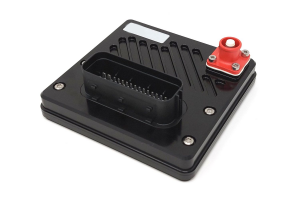
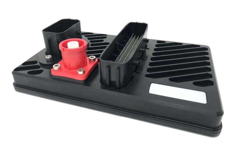
High power motorsport Power Distribution Unit (PDU). Combines a robust billet aluminium case and the very latest power driving technology with the highest efficiency in the industry. A total of 34 output channels with a max current capacity of 350A

Outputs:

 34 main Power Outputs, 20 outputs rated to 30A, 14 outputs rated to 15A
 10 multifunction high side, low side, PWM, H-Bridge, soft start outputs
(peak current 100A)
 20 High Side outputs (peak current 125A)

 4 Additional Low Side Outputs (PWM capable)
 Output teaming to support very high current devices
 All outputs short circuit and thermally protected with multi-stage in-rush control
 Combined diagnostic output with reset input
 Up to 64 soft outputs via CAN

Inputs:

 16 physical switch inputs or, when slaved, general purpose analogue sensor inputs including:
 8x frequency measurement inputs (4 optionally bi-polar)
 software selectable 3k ohm pull-up resistors
 4x inputs capable of programmable “wake up” functionality
 Dedicated wake pin
 Up to 64 soft inputs via CAN with configurable validation and debounce time

Comms:

 x2 100Mbit/s full duplex Ethernet (can be used as Ethernet switch)
 x3 CAN 2.0B
 RS232C serial interface
 LIN Bus

Physical:

 6.5V to 40V input voltage
 Dedicated 12V logic power input
 Regulated 5V sensor supply output with short circuit protection

 2 Leavyseal connectors with a total of 113 pins
 x1 Deutsch HDP 47way Connector
 Amphenol SurLok Power Stud
 Machined Aluminium enclosure
 200x130x54mm (including connectors)
 850g
 Operating Temperature -20 to +85C

Additional information

Software

http://www.syvecs.com/forum/viewtopic.php?f=8&t=122

Wiring Guide

http://www.syvecs.com/downloads/PDUx3.pdf