Page 2 of 2
Re: S6GP Speed Input Signal To Different Output Signal
Posted: Tue Jan 24, 2017 3:10 pm
by e_dale2000
I looked at the JayCar Speedo Corrector the other day. would this work from the output ? i was under the impression it was for speed correction if you had bigger wheels/different diff etc.
https://www.jaycar.com.au/corrector-spe ... e/p/AA0376
The Dakota signal converter seems to do everything i need i was just wondering if its possible to do it more elegantly with the ecu than put another piece of kit in there or spend silly money on a digi dash when only speed is an issue on the cluster.
http://www.dakotadigital.com/index.cfm/ ... prd126.htm
thanks again for the replies

Re: S6GP Speed Input Signal To Different Output Signal
Posted: Tue Jan 24, 2017 5:27 pm
by stevieturbo
It is...but as it is a universal unit, it can receive various pulse types... adjust and then transmit various pulse types to suit whatever speedo you may be using.
So in effect it could receive a square wave type signal and then adjust the pulse count and re-transmit the new signal in a VR type form.
Have you tried connecting your existing speed trigger ( and ground ) to the speedo to see if it works ?
Re: S6GP Speed Input Signal To Different Output Signal
Posted: Tue Jan 24, 2017 6:02 pm
by Slowie
The Nissan speedo is very easy to sort out. My S13 speedo (same 90s tech) is driven by my trip meter output perfectly. Just needs one small tweak.
Will post more details when I'm home later.
Re: S6GP Speed Input Signal To Different Output Signal
Posted: Tue Jan 24, 2017 9:16 pm
by Slowie
The Nissan speedo needs a sine wave yes, but it doesn't need to be a perfect sine wave. A poor quality sine wave will work, as long as it crosses 0V. The speedo triggers on 0V, and needs 10000 pulses per km, or 16000 pulses per mile. My pulses per meter is set to 10 under Output Functions->Trip Meter for my km/h speedo.
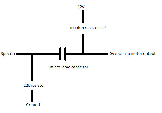
You can use the following circuit to convert the digital trip meter output into a sine-ish wave which will trigger the speedo.

- Nissan Speedo drive.png (5.74 KiB) Viewed 22233 times
You need a 100ohm 12V pullup, then a simple capacitor and pulldown resistor. You may need to play with the value of the pullup resistor (hence the asterisks), to get it working cleanly. I might have used a 1K resistor, can pull the dash to check if you don't come right.
Re: S6GP Speed Input Signal To Different Output Signal
Posted: Thu Jan 26, 2017 1:08 pm
by e_dale2000
Thank you very much for the replies !
I will pass the information along to Martin and hopefully he can sort it out when i get my remap done in a few weeks.
Although I might have a play at weekend if i have time to grab the bits from the local shop

thanks again for your responses you have all been extremely helpful!
